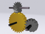
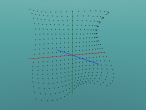
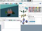
involute gear
It turned out that producing a set of involute gears requires quite a bit of geometry in addition to involutes.
It is useful to get familiar with gear terminology and with the special properties of an involute of a circle. In particular, it is necessary to figure the angular width of a tooth at the base circle which is where the involute, curved section of a tooth begins.
So there is a lot to explain in this logo program.
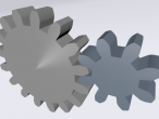
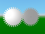
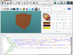
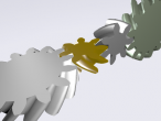
Next steps include to figure out why there is a slight overlap between teeth from both gears, and to make the gears 3d with some depth. Is there a way to use the extrusion functionality of x3d ?
[Update: the initial configuration was slightly off. Scene and logo updated.]
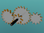
Well, here is the logo:
; involute: draw involute ; rb: base radius ; limit: max. generating angle ; steps: number of segments on involute to draw TO involute :rb :limit :steps LOCALMAKE "start POS LOCAL "end LOCALMAKE "i 0 LOCALMAKE "step 0.5 * :limit / :steps ;(print :step :steps) PU REPEAT ABS(:steps) [ MAKE "i :i + :step ;move along circle LT :step FD 2 * :rb * SIN :step ;find tangent RT 180 - :step ;unroll string FD 2 * :i * :deg2rad * :rb MAKE "end POS ;connect end points PD SETPOS :start ;move back PU SETPOS :end MAKE "start :end BACK 2 * :i * :deg2rad * :rb ;turn forward LT 180 ;nextcolor ] SETPOS :start END ; gearinvolute: draw involute side of gear tooth ; rb: base radius ; PA: pressure angle ; P: diametral pitch ; steps: number of subdivisions TO gearinvolute :rb :PA :P :steps LOCALMAKE "a 1 / :P LOCALMAKE "ro ( :rb / COS :PA ) + :a ;calculate generating angle for top of tooth ;(needs drawing) LOCALMAKE "l2 :ro ^ 2 - :rb ^ 2 LOCALMAKE "limit ( SQRT :l2 ) / :rb involute :rb (:limit / :deg2rad) :steps END ; geartooth: draw one full tooth ; rp: radius of pitch circle ; PA: pressure angle ; P: diametral pitch ; hdelta: half angular base width (expected) ; segments: number of subdivisions on each side TO geartooth :rp :PA :P :hdelta :segments LOCALMAKE "rb :rp * COS :PA LOCALMAKE "clr (2.157 - 2) / :P ;coarser 20P LOCALMAKE "ddif (1/:P + :clr) - (:rp - :rb) RT 90 FD :ddif LT 90 ; save position LOCALMAKE "base POS LOCALMAKE "head HEADING gearinvolute :rb :PA :P :segments ;mirror ;or draw with negative step LOCALMAKE "top POS SETPOS :base SETHEADING :head ;turn and move to other side of tooth ;half angular base width LT :hdelta FD 2 * :rb * ( SIN ( :hdelta ) ) LT :delta / 2 ;save pos MAKE "base POS MAKE "head HEADING ;draw other side gearinvolute :rb :PA :P :segments * -1 ;connect sides at top PD SETPOS :top PU SETPOS :base SETHEADING :head PD LT 90 FD :ddif RT 90 END ; gear: draw involute gear ; rp: radius at pitch circle ; PA: pressure angle ; P: number of teeth normalized by pitch diameter ; segments: subdivions on each involute side of each tooth TO gear :rp :PA :P :segments LOCALMAKE "cpitch :PI / :P LOCALMAKE "apitch (:cpitch / :rp) / :deg2rad LOCALMAKE "N :P * :rp * 2 LOCALMAKE "rb :rp * COS :PA LOCALMAKE "clr (2.157 - 2) / :P ;coarser 20P LOCALMAKE "ded (1/:P + :clr) LOCALMAKE "rr :rp - :ded ;this is the main calculation ;for angular base width delta ;(needs drawing) LOCALMAKE "alpha ( TAN :prA ) / :deg2rad LOCALMAKE "beta :alpha - :prA LOCALMAKE "delta ( 0.5 * :apitch ) + ( 2 * :beta ) PU RT 90 FD :rr LT 90 PD REPEAT :N [ geartooth :rp :PA :P :delta / 2 :segments PD LT (:apitch - :delta) / 2 FD 2 * :rr * SIN ((:apitch - :delta) / 2) LT (:apitch - :delta) / 2 NEXTCOLOR ] PU LT 90 FD :rr RT 90 END ; mycircle: draw circle ; crd: circle radius TO mycircle :crd PU RT 90 FD :crd LT 90 PD REPEAT 180 [ LT 2 FD 2 * :crd * SIN ( 2 ) LT 2 ] PU LT 90 FD :crd RT 90 PD END ;involute (for gears) ;comprehensive guide ;http://bostongear.com/pdf/gear_theory.pdf RESET CLEARSCREEN SETBACKGROUND 33 RU 90 PD MAKE "PI 4 * RADARCTAN(1) MAKE "deg2rad :PI / 180 MAKE "prA 14.5 MAKE "piR 0.5 MAKE "pitch 16 ;mycircle :baR ;mycircle :piR ;mycircle :ouR TRANSFORM SET OBJECT "rotation [0 0 1 0] MAKE "gear1 OBJECT SET :gear1 "center POS SETPARENT OBJECT gear :piR :prA :pitch 10 SETPARENT "root MAKE "piR2 0.25 PU RT 90 FD :piR + :piR2 LT 90 TRANSFORM SET OBJECT "rotation [0 0 1 0] MAKE "gear2 OBJECT SET :gear2 "center POS SETPARENT OBJECT gear :piR2 :prA :pitch 10 SETPARENT "root ;adjust by beta, angular distance between point at base and point at pitch circle MAKE "beta (TAN :prA) - (:prA * :deg2rad) SET :gear1 "rotation (LIST 0 0 1 -:beta) SET :gear2 "rotation (LIST 0 0 1 :PI/:pitch/:piR2 - :beta) MAKE "period1 60 SPIN :gear1 "tl :period1 SPIN :gear2 "tr :period1 * :piR2/:piR PU SHOWALL
- aplesch's blog
- Login or register to post comments
- 19171 reads
Comments
gear ratio
Yes, it should be possible to produce any standard involute gear. Gears fit together if they same pitch.
The velocity of the gear rotations needs to be inversely proportional the pitch radius. It is easiest to think about wheels instead. For a unit period of time both wheels need to cover the same distance on their circumference.
Good point about the possible lack of synchronization for the spinning of the gears. I will try to use just one time sensor, so both orientation interpolator should get the same input.
TimeSensor
Another way to do can be changing the startTime of the TimeSensors (if two). TimeSensor is fully implemented in X3DOM. The fields startTime and stopTime etc. will not show in DOM but I remembered the SET command can still get it to work.