Spur gears
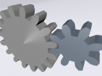
Finally, not perfect at all but working gear set in 3D. Thanks to asplech's blog about involute gear and this Spur Gear document, I finally get to know better about these cogged wheels.
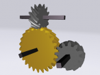
The 3D world below shows 4 gears meshing together. Because they have different number of teeth, they would have created some mechanical advantages/disadvantages in changing directions, speeds, and forces. Click on the cylinder can start or stop the animation. You can also navigate and zoom in to see the gears are actually meshing well.
The Logo program is commented below. I thought that I can make it short but still end up with almost 200 lines. The good thing is that you can change the pressure angle, diametral pitch, teeth number, and thickness. The gear generated should have same tooth length and as long as they have the same pressure angle and diametral pitch, they should mesh well. However, it will be a little bit tricky to spin at the right speed and direction, particularly when the number of teeth is an odd number.
; Spur Gear http://www.gearseds.com/files/6.3.1_Gear_Terms_Lesson_rev3.pdf RESET ; Global parameters for meshing gears MAKE "pa 20 ; pressure angle, common angles are 14.5, 20 MAKE "dp 24 / 2.54 ; diametral pitch = tn / pd (in inch) ; below are derived from global parameters above MAKE "add 1 / :dp ; addendum MAKE "ddd 1.157 / :dp ; dedendum ; tn: number of teeth ; thickness: thickness of gear ; clearance: not implemented in this prototype ; gear3d will output the parent transform id for the gear. TO gear3d :tn :thickness ; find four key diamater from outside to inside MAKE "od (:tn + 2) / :dp ; overall diameter of the gear = (tn+2)/dp MAKE "or :od / 2 ; overall radius MAKE "pd :tn / :dp ; pitch diameter MAKE "pr :pd / 2 ; pitch radius MAKE "bd :pd * COS :pa ; base diameter MAKE "br :bd / 2 ; base radius MAKE "rd (:tn - 2) / :dp ; root diameter MAKE "rr :rd / 2 ; root radius ; other derivitives MAKE "ta 360 / :tn ; angle between two teeth ; oc, oc1: outside circle coordinates array ; pc, pc1: pitch circle coordinates array ; bc, bc1: base circle coordinates array ; rc, rc1: root circle coordinate array MAKE "oc [] MAKE "oc1 [] MAKE "pc [] MAKE "pc1 [] MAKE "bc [] MAKE "bc1 [] MAKE "rc [] MAKE "rc1 [] ; record initial pos and ori MAKE "pos POS MAKE "ori ORI RU 90 ; collect coordinates REPEAT :tn [ ; collect oc, oc1 LT :ta/14 FD :or QUEUE "oc POS RD 90 FD :thickness QUEUE "oc1 POS BK :thickness RU 90 BK :or RT :ta/14*2 FD :or QUEUE "oc POS RD 90 FD :thickness QUEUE "oc1 POS BK :thickness RU 90 BK :or LT :ta/14 ; collect pc, pc1 LT :ta/4 FD :pr QUEUE "pc POS RD 90 FD :thickness QUEUE "pc1 POS BK :thickness RU 90 BK :pr RT :ta/4*2 FD :pr QUEUE "pc POS RD 90 FD :thickness QUEUE "pc1 POS BK :thickness RU 90 BK :pr LT :ta/4 ; collect bc, bc1 LT :ta/3.6 FD :br QUEUE "bc POS RD 90 FD :thickness QUEUE "bc1 POS BK :thickness RU 90 BK :br RT :ta/3.6*2 FD :br QUEUE "bc POS RD 90 FD :thickness QUEUE "bc1 POS BK :thickness RU 90 BK :br LT :ta/3.6 ; collect rc, rc1 LT :ta/3.4 FD :rr QUEUE "rc POS RD 90 FD :thickness QUEUE "rc1 POS BK :thickness RU 90 BK :rr RT :ta/3.4*2 FD :rr QUEUE "rc POS RD 90 FD :thickness QUEUE "rc1 POS BK :thickness RU 90 BK :rr LT :ta/3.4 RT :ta ] SETPOS :pos SETHEADING :ori FD :thickness/2 MAKE "posCenter POS FD :thickness/2 MAKE "pos1 POS ; draw gear SETPOS :pos SETHEADING :ori TRANSFORM MAKE "obj OBJECT SETPARENT :obj SET OBJECT "center :posCenter FACE PCOFF ; draw first cross section SETMAT 0 33 SETTR 200 ; make it a little transparent PD SETPOS LAST :rc REPEAT :tn [ MAKE "n 2 * REPCOUNT SETPOS ITEM :n-1 :rc SETPOS ITEM :n-1 :bc SETPOS ITEM :n-1 :pc SETPOS ITEM :n-1 :oc SETPOS ITEM :n :oc SETPOS ITEM :n :pc SETPOS ITEM :n :bc SETPOS ITEM :n :rc ] PU SET OBJECT "rotation :ori SET OBJECT "center :pos ; draw second cross section SETPOS :pos1 PD SETPOS LAST :rc1 REPEAT :tn [ MAKE "n 2 * REPCOUNT SETPOS ITEM :n-1 :rc1 SETPOS ITEM :n-1 :bc1 SETPOS ITEM :n-1 :pc1 SETPOS ITEM :n-1 :oc1 SETPOS ITEM :n :oc1 SETPOS ITEM :n :pc1 SETPOS ITEM :n :bc1 SETPOS ITEM :n :rc1 ] PU SET OBJECT "rotation :ori SET OBJECT "center :pos ; draw side faces SETPOS FIRST :rc SETMAT 0 25 PD REPEAT :tn [ MAKE "n 2 * REPCOUNT SETPOS ITEM :n-1 :rc1 SETPOS ITEM :n-1 :bc1 SETPOS ITEM :n-1 :bc JUMP SETPOS ITEM :n-1 :bc1 SETPOS ITEM :n-1 :pc1 SETPOS ITEM :n-1 :pc JUMP SETPOS ITEM :n-1 :pc1 SETPOS ITEM :n-1 :oc1 SETPOS ITEM :n-1 :oc JUMP SETPOS ITEM :n-1 :oc1 SETPOS ITEM :n :oc1 SETPOS ITEM :n :oc JUMP SETPOS ITEM :n :oc1 SETPOS ITEM :n :pc1 SETPOS ITEM :n :pc JUMP SETPOS ITEM :n :pc1 SETPOS ITEM :n :bc1 SETPOS ITEM :n :bc JUMP SETPOS ITEM :n :bc1 SETPOS ITEM :n :rc1 SETPOS ITEM :n :rc JUMP IFELSE :n+1 > COUNT :rc [ SETPOS ITEM :n :rc1 SETPOS FIRST :rc1 SETPOS FIRST :rc ] [ SETPOS ITEM :n :rc1 SETPOS ITEM :n+1 :rc1 SETPOS ITEM :n+1 :rc JUMP ] ] PU SET OBJECT "rotation :ori SET OBJECT "center :posCenter ; draw pitch circle LINE SETPOS LAST :pc PD REPEAT :tn [ MAKE "n 2 * REPCOUNT SETPOS ITEM :n-1 :pc SETPOS ITEM :n :pc ] PU ; return to starting pos and ori SETPOS :pos SETHEADING :ori SETPARENT "root OUTPUT :obj END TO getPR :tn OUTPUT :tn / :dp / 2 ; output pitch radius END CLEAN HOME RU 90 SETSCALE .2 4 .2 SETMAT 0 30 CYLINDER RESET HOME ; gear3d :tn :thickness MAKE "g1n 20 MAKE "g2n 11 MAKE "g3n 8 MAKE "g4n 14 MAKE "gear1 gear3d :g1n .2 RT 90 FD getPR :g1n FD getPR :g2n LT 90 TR 90 - 180/:g2n MAKE "gear2 gear3d :g2n .2 ; collect rotation value MAKE "g2r [] QUEUE "g2r ORI REPEAT 4 [ TL 90 QUEUE "g2r ORI ] HOME BK 1 MAKE "gear3 gear3d :g3n .2 LT 90 FD getPR :g3n FD getPR :g4n RT 90 ; tr 90 - 180/:g2n MAKE "gear4 gear3d :g4n .2 SPIN :gear1 "tr 60 SPIN :gear2 "tl 60 / (:g1n/:g2n) SET WORD "spin_oi_ :gear2 "keyvalue :g2r SPIN :gear3 "tr 60 SPIN :gear4 "tl 60 / (:g3n/:g4n) TOGGLE "act1 WORD "spin_ts_ :gear1 "enabled TOGGLE "act2 WORD "spin_ts_ :gear2 "enabled TOGGLE "act3 WORD "spin_ts_ :gear3 "enabled TOGGLE "act4 WORD "spin_ts_ :gear4 "enabled CLICK "obj_0 "act1 CLICK "obj_0 "act2 CLICK "obj_0 "act3 CLICK "obj_0 "act4
The gear tooth is not as smooth as the involute gear. But it demonstrates a Logo way to collect circle coordinates and geometric shapes created later by connecting these coordinates. Same principle can be applied when I have implemented EXTRUSION, 2D coordinates can be collected as the cross section and be extruded. The rotation (SPIN) of the 11 teeth gear is a bit tricky. Line 175-176 collects the orientation and apply to the OrientationInterpolator's keyvalue in order to syn witht the gear ratio (applied to TIMESENSOR's cycleInterval).
Files: gear3d.x3d gear3d_proto1.logo
- Andy's blog
- Login or register to post comments
- 11266 reads
Comments
Mesh
The combined movement of the gears looks really good. Is it the example from the gear document for teaching ?
Good idea to customize the keyvalues. I ended up using two transforms.
Teaching gears
The gear document for teaching is a surprise I found online. It even maps to the English, Mathematics and Science and Technology standards for Year 9-12 in the US. One of my major goals of VRMath2 is to support the teaching and learning in STEM areas. That Spur Gear teaching document is a good example for this website.
I just noticed that it has many examples of meshing gears but I did not follow them when I did. I just want to try how to mesh gears with different numbers of teeth. A 3D world like that can teach/learn about gear ratio, rotation speeds and directions, which are topics in STEM. Of course, the best way of learning is for students to go though the construction as we did, not just see what we have created.
Yes, two transforms will work.. but I wonder why not one parent transform in my case... My gear coordinates are already rotated. This is something I need to look into...
You have spent much time on VRMath2 sites, which I really appreciate. I hope you found VRMath2 interesting and useful for some of your project.
Converted
I tried to import this gear3d.x3d into Blender and MeshLab and they both did, including the cylinder. This means that I can export as STL or PLY for 3D printing of gears.