Virtual Robotic Arm with Controls
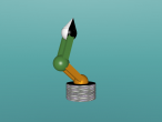
Having blogged an animated robotic arm, I thought that I can easily create another version of virtual robotic arm, which can be controlled by sliders. And yes, it was easily done. In VRMath2 Editor, after running the robotic_arm.logo, the X3D codes in HTML5 can be viewed and copied from the HELP menu --> Debug --> View X3D in DOM. Note that the X3D codes copied from DOM (document object model) are in HTML5. This is different from the X3D file published in VRMath2 Editor. The robotic_arm.x3d published is in standard X3D format, which is in xhtml (XML). If using X3DOM to display and manipulate/control the 3D scene in HTML5, copy the X3D codes from DOM and pasted into your HTML file would be easier.
I used my preferred coding editor Coda 2 in my MBP, and created a signle webpage of this virtual robotic arm. You can click on that link, view its source codes if you are a programmer and would like to edit. Below I also include the HTML+Javascript (my privilege as the editor of this website), so you can have a play straight away here.
Robotic Arm Data (initial)
Base (0,0,0) | Shoulder (0,0.3,0) | Elbow (0,1.3,0) | Wrist (0,2.3,0) | Tip (0,2.85,0)
Upper arm length (shoulder to elbow): 1 | Lower arm to Tip length (elbow to tip): 1.55
Controls
| Base: | degrees | ||
|---|---|---|---|
| Shoulder: | degrees | ||
| Elbow: | degrees | ||
| Wrist: | degrees |
Tracking
Elbow Centre: X: Y: Z:
Tip point: X: Y: Z:
|
I used simple trignometry to calculate the tip point coordinate. It took me a while to think through despite this simple 3 degrees of freedom arm. Below are the key javascript codes for working out both the elbow and tip coordinates.
// calculate elbow centre, length of upper arm is 1
d_sh = document.getElementById("shoulderValue").value; // get shoulder rotation in degrees
r_sh = Math.PI * d_sh / 180; // shoulder rotation in radian
elp.z = Math.sin(-r_sh);
elp.y = Math.cos(r_sh) + shp.y;
// calculate tip point
d_el = document.getElementById("elbowValue").value; // get elbow rotation in degrees
r_el = Math.PI * d_el / 180;
// 1.55 is the distance between tip point and elbow centre (lower arm length)
tip.z = 1.55 * Math.sin(-(r_sh+r_el)) + elp.z;
tip.y = 1.55 * Math.cos(r_sh+r_el) + elp.y;
// calculate base effect on elbow and tip
d_ba = document.getElementById("baseValue").value; // get base rotation in degrees
r_ba = Math.PI * d_ba / 180;
// base effect on elbow
elp.x = elp.z * Math.sin(-r_ba);
elp.z = elp.z * Math.cos(r_ba);
// base effect on tip
tip.x = tip.z * Math.sin(-r_ba);
tip.z = tip.z * Math.cos(r_ba);
Later I googled to find that the robotic arm movement are called forward kinematics. In engineering, there are different solutions of mathematics to workout the end point (tip). For example, trignometry is one way, and most others are using 3D rotation matrices (trignometry is included).
Robotic arms could be a good context for secondary students to problem-solve using trignometry and matrices. The many different types and different numbers of degrees of freedom (i.e., axes of rotations) of robotic arms provide opportunities for learners to apply further their learning of mathematics. In my maker projects, I have also made a robotic arm, and will soon apply the mathematics to control this real robotic arm.
In this virual control, I have worked out from the rotations to calculate the end tip point. Similarly, it can also be given an end point and the arm could probably have a few different rotations to get to the specified end point. This seems to be an interesting project and mathematics, what do you think?


