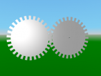
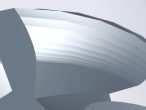
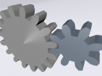
3d involute gears
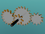
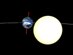
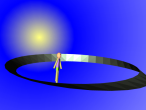
As an update to the 2d involute (curved teeth) gears, I modified the program to produce 3d (extruded) gears. This required a change in drawing tactics.
First, the turtle moves along the gear without drawing anything but only recording its position into a growing list of coordinates. This actually simplified some aspects of drawing the gear since less temporary saving of positions was required. Second, the recorded path is used to generate faces away from the path going segment by segment. The reduce command was convenient for this procedure since it supplies two neighbouring values of a list. Finally, nested transforms are used to adjust the initial rotation of the gears so they mesh together (inner transform) and to spin the adjusted gears (outer transform). To avoid any intersection of the gears, the second gear is moved a small bit farther away from the first gear than strictly necessary. I believe, real small gears tend to require "undercuts" to avoid the same issue.
[Next, I would like to fill in the front and back. Due to the curved shape of the teeth, this will require some more sophisticated face generation.]
Update: front and back are now closed, and some general changes.
Here is the updated, commented logo program:
; involute: draw involute ; rb: base radius ; limit: max. generating angle ; steps: number of segments on involute to draw ; returns list of positions: top is first TO involute :rb :limit :steps LOCALMAKE "start POS LOCALMAKE "i 0 LOCALMAKE "step 0.5 * :limit / :steps LOCALMAKE "coords [] PUSH "coords POS PU REPEAT ABS(:steps) [ ;push "coords :start MAKE "i :i + :step ;move along circle LT :step FD 2 * :rb * SIN :step ;find tangent RT 180 - :step ;unroll string FD 2 * :i * :deg2rad * :rb ;make "start pos ;record position PUSH "coords POS BACK 2 * :i * :deg2rad * :rb ;turn forward LT 180 ] SETPOS :start OUTPUT THING "coords END ; gearinvolute: draw involute side of gear tooth ; rb: base radius ; PA: pressure angle ; P: diametral pitch ; steps: number of subdivisions ; returns list of position from landing to base TO gearinvolute :rb :PA :P :steps LOCALMAKE "a 1 / :P LOCALMAKE "ro ( :rb / COS :PA ) + :a ;calculate generating angle for top of tooth ;(needs drawing) LOCALMAKE "l2 :ro ^ 2 - :rb ^ 2 LOCALMAKE "limit ( SQRT :l2 ) / :rb LOCALMAKE "coords involute :rb (:limit / :deg2rad) :steps OUTPUT THING "coords END ; geartooth: draw one full tooth ; rp: radius of pitch circle ; PA: pressure angle ; P: diametral pitch ; hdelta: half angular base width (expected) ; segments: number of subdivisions on each side ; returns list of positions from root to landing to root TO geartooth :rp :PA :P :hdelta :segments LOCALMAKE "rb :rp * COS :PA LOCALMAKE "clr (2.157 - 2) / :P ;coarser 20P LOCALMAKE "ddif (1/:P + :clr) - (:rp - :rb) LOCALMAKE "coords [] PUSH "coords POS ; record straight edge RT 90 FD :ddif PUSH "coords POS LT 90 ; save position LOCALMAKE "base POS LOCALMAKE "head HEADING ; record side MAKE "coords SENTENCE ( gearinvolute :rb :PA :P :segments ) :coords ;record with negative step LOCALMAKE "top POS SETPOS :base SETHEADING :head ;turn and move to other side of tooth ;half angular base width LT :hdelta FD 2 * :rb * ( SIN ( :hdelta ) ) LT :delta / 2 ;save pos MAKE "base POS MAKE "head HEADING ;draw other side ;prepend reverse MAKE "coords SENTENCE REVERSE ( gearinvolute :rb :PA :P :segments * -1 ) :coords ;return to base SETPOS :base SETHEADING :head ;record straight edge LT 90 FD :ddif PUSH "coords POS RT 90 OUTPUT THING "coords END ; gear: draw involute gear ; rp: radius at pitch circle ; PA: pressure angle ; P: number of teeth normalized by pitch diameter ; segments: subdivions on each involute side of each tooth ; returns list of positions TO gear :rp :PA :P :segments LOCALMAKE "cpitch :PI / :P LOCALMAKE "apitch (:cpitch / :rp) / :deg2rad LOCALMAKE "N :P * :rp * 2 LOCALMAKE "rb :rp * COS :PA LOCALMAKE "clr (2.157 - 2) / :P ;coarser 20P LOCALMAKE "ded (1/:P + :clr) LOCALMAKE "rr :rp - :ded ;this is the main calculation ;for angular base width delta ;(needs drawing) LOCALMAKE "alpha ( TAN :prA ) / :deg2rad LOCALMAKE "beta :alpha - :prA LOCALMAKE "delta ( 0.5 * :apitch ) + ( 2 * :beta ) LOCALMAKE "coords [] ; move from center to root PU RT 90 FD :rr LT 90 REPEAT :N [ ;tooth from root to root MAKE "coords SENTENCE ( geartooth :rp :PA :P :delta / 2 :segments ) :coords ;advance to root of next tooth LT (:apitch - :delta) / 2 FD 2 * :rr * SIN ((:apitch - :delta) / 2) LT (:apitch - :delta) / 2 ] ;close up PUSH "coords POS LT 90 FD :rr RT 90 OUTPUT THING "coords END TO drawline :positions PU SETPOS FIRST :positions PD FOREACH "setpos :positions END TO plate :positions :segments LOCALMAKE "pcenter [0 0 0] ;draw skinny triangles ;or fill teeth ;fill circle PU SETPOS FIRST :positions FACE PCOFF PD SHOW REDUCE "skinny :positions PU LINE OUTPUT OBJECT END TO skinny :p1 :p2 JUMPPOS :p1 SETPOS :p2 SETPOS :pcenter OUTPUT :p2 END TO gear3d :positions :segments :width fence :positions :width COPY plate :positions :segments PASTE ; (does not update object; fixed) ; localmake "pasted word "obj_ (reduce "word bf bf bf bf object) + 1 SET OBJECT "rotation [0 0 1 0] SET OBJECT "translation ( LIST 0 0 :width ) END TO fence :positions :width PU SETPOS FIRST :positions FACE PCOFF PD SHOW REDUCE "quad :positions PU LINE END TO quad :p1 :p2 JUMPPOS :p1 SETPOS :p2 SETPOS offsetz :p2 :width SETPOS offsetz :p1 :width OUTPUT :p2 END TO offsetz :point :offset OUTPUT SENTENCE BUTLAST :point (SUM LAST :point :offset) END ;involute (for gears) ;comprehensive guide ;http://bostongear.com/pdf/gear_theory.pdf ;TODO create gears always around origin ;TODO use transforms to offset ;TODO fill front and back: tooth by tooth and disk RESET CLEARSCREEN SETBACKGROUND 34 POINTLIGHT RU 90 MAKE "PI 4 * RADARCTAN(1) MAKE "deg2rad :PI / 180 MAKE "prA 14.5 MAKE "piR 0.5 MAKE "piR2 0.25 MAKE "pitch 16 MAKE "gear1center POS MAKE "gear1line gear :piR :prA :pitch 10 MAKE "gear2line gear :piR2 :prA :pitch 10 RT 90 FD :piR + :piR2 + :piR2/20 ;some slack LT 90 MAKE "gear2center POS SETPOS :gear1center TRANSFORM MAKE "gear1spin OBJECT SET :gear1spin "rotation [0 0 1 0] SET :gear1spin "center :gear1center SETPARENT :gear1spin TRANSFORM MAKE "gear1 OBJECT SET :gear1 "rotation [0 0 1 0] SET :gear1 "center :gear1center SETPARENT :gear1 SETMATERIAL 3 33 gear3d :gear1line 10 -0.2 SETPARENT "root TRANSFORM MAKE "gear2spin OBJECT SET :gear2spin "rotation [0 0 1 0] SET :gear2spin "center :gear1center SET :gear2spin "translation :gear2center SETPARENT :gear2spin TRANSFORM MAKE "gear2 OBJECT SET :gear2 "rotation [0 0 1 0] SET :gear2 "center :gear1center SETPARENT :gear2 SETMATERIAL 3 28 gear3d :gear2line 10 -0.2 SETPARENT "root MAKE "beta (TAN :prA) - (:prA * :deg2rad) ;inital rotations SET :gear1 "rotation (LIST 0 0 1 -:beta) SET :gear2 "rotation (LIST 0 0 1 :PI/:pitch/:piR2 - :beta) MAKE "period1 60 SPIN :gear1spin "tl :period1 SPIN :gear2spin "tr :period1 * :piR2/:piR PU SHOWALL
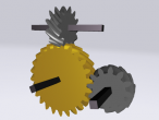
Here is an example with pitch 32 (more teeth) and a pressure angle of 20. It shows the limitations of the skinny triangle approach.
And here the same gears with improved front and back mesh:
Only a few changes were necessary. First, I changed the data structure of the gear profile from a flat list of positions to positions grouped by tooth:
TO gear :rp :PA :P :segments LOCALMAKE "cpitch :PI / :P LOCALMAKE "apitch (:cpitch / :rp) / :deg2rad LOCALMAKE "N :P * :rp * 2 LOCALMAKE "rb :rp * COS :PA LOCALMAKE "clr (2.157 - 2) / :P ;coarser 20P LOCALMAKE "ded (1/:P + :clr) LOCALMAKE "rr :rp - :ded ;this is the main calculation ;for angular base width delta ;(needs drawing) LOCALMAKE "alpha ( TAN :prA ) / :deg2rad LOCALMAKE "beta :alpha - :prA LOCALMAKE "delta ( 0.5 * :apitch ) + ( 2 * :beta ) LOCALMAKE "coords [] ; move from center to root PU RT 90 FD :rr LT 90 REPEAT :N [ ;tooth from root to root ; CHANGED here to put list new tooth as list in front MAKE "coords FPUT ( geartooth :rp :PA :P :delta / 2 :segments ) :coords ;advance to root of next tooth LT (:apitch - :delta) / 2 FD 2 * :rr * SIN ((:apitch - :delta) / 2) LT (:apitch - :delta) / 2 ] ;close up ;CHANGED not required any more ;push "coords pos LT 90 FD :rr RT 90 OUTPUT THING "coords END
Then it was a matter of adjusting the front and back plate drawing procedure to draw a polygon per tooth and then a large circular polygon for the center:
TO polygon :positions JUMPPOS FIRST :positions FOREACH "setpos BF :positions END TO firstlast :positions OUTPUT LIST FIRST :positions LAST :positions END TO plate :positions :segments PU SETPOS FIRST FIRST :positions FACE PCOFF PD ;fill teeth FOREACH "polygon :positions ;fill circle polygon REDUCE "sentence MAP "firstlast :positions PU LINE OUTPUT OBJECT END
Finally, a flattening transformation of the gear profile data structure is required to be able to continue to use the fence procedure:
TO gear3d :positions :segments :width LOCALMAKE "posflat FPUT (LAST LAST :positions) (REDUCE "sentence :positions) fence :posflat :width COPY plate :positions :segments PASTE SET OBJECT "rotation [0 0 1 0] SET OBJECT "translation ( LIST 0 0 :width ) END
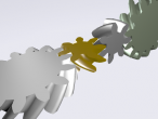
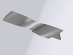
Here is a picture of the new front and back mesh which x3dom generates for the provided polygons:
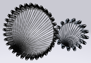
Fig. 1: Triangulation front and back plate polygons
- aplesch's blog
- Login or register to post comments
- 23929 reads
Comments
some issues for forum discussion
When I change your code:
to
It seems to work the same. Have I missed something? Could you give an example code?
The triangle approch does work well. I can see the work in progress and the two crosssections are coming up..
Do you mean to direct ly edit the x3d codes (say in the debug -> view x3d in dom)? Or do you mean those GUIs for direct manipulation of objects in 3D such as Blender or MeshLab?
Direct coding of x3d may pose some security issues online. It will require more considerations when enabling x3d codes manipulation. I know that will be welcomed by x3d programmers. I am unable to commit time for GUIs for direct manipulation in 3D. And in fact, that is not my purpose at all. The Logo programming is almost the key components for VRMath2 to be an educational tool... (unfortunately, it has not been recognised even by education people yet). I certainly won't give up Logo in VRMath2, but users (including school children) can certainly ignore it or don't have to use it. But then the ability to create 3D worlds will be very limited by my limited GUIs.
x3d editor
I agree that logo is really nice for teaching and did not mean to suggest to abandon it at all.
For a x3d focus, perhaps a really simple world construction workspace mode would be the only thing required: 3d world, object inspector, object tree and updating (debug) non editable x3d code window. This way, a x3d learner gets a pretty quick idea how x3d works in principle. An advanced mode could perhaps include the behaviour and animator windows once they are functional. So I think using the existing GUI would not be too limiting at all. Actually, making it a bit more restrictive (simplified menu, less tools) for x3d could be advantageous for learning.
good suggestions
Thanks for the suggestions. I will try to create such as workspace. :-)
PS: from today I will enter assignment marking mode and may not be responsive until next week..
thing
Yes, I did some tests and it does work. Hm, perhaps this commit fixed it:
https://github.com/inexorabletash/jslogo/commit/61639ded891828a6dd8a9738...
I also found that I have to use the list command to construct lists if a member needs to be evaluated: [ 1 :myvar 3]
But that may be as intended, eg. everything wthin brackets is quoted.
Andreas
update logojs
My logojs was base on 2014-01-27 version so commits after are not included in my VRMath2 logo...
This is another job for me to do and test...